1. Module introduction
ETS (Emergency Trip System) is the abbreviation of the steam turbine crisis trip system. It is the most important part of the steam turbine protection. It is the outlet for the electric trip of the steam turbine. Its operation safety directly affects the safe operation of the steam turbine.
The LN30C three-redundant ETS module is an important part of the LN3000 DCS dispersed control system. It can complete the switching control functions of all electric valves during the critical tripping control process of the turbine, including completing the data acquisition, processing, calculation of the switching quantity and real-time output of the switching quantity, and transmit the relevant data to the central control operation room through communication. The switching signals that can be detected include: steam turbine speed, lubricating oil pressure, condenser vacuum, DEH fault, bearing vibration, axial displacement, thermal expansion, differential increase, bearing return oil temperature, high water level, exhaust chamber pressure, etc. When the monitored parameters exceed the specified value, the ETS device outputs a trip signal to the trip solenoid valve. The trip solenoid valve unloads the security oil of the security system, so that the main air valve and regulating valve of the turbine are quickly closed, completing the steam turbine trip function, and implementing emergency trips to ensure the safety of the unit equipment and personal safety to avoid serious consequences.
1.1 Equipment Features
² Microprocessor technology and large-scale programmable logic device processing technology
² Seamless connection with DEH and DCS
² High reliability (three redundancy), quick response
² 41 switch inputs, 15 logic outputs
² Each module is divided into a safety working part and a monitoring part to ensure system reliability
² Turn off protection, first-out instructions, *** record
² Delayed jitter removal
² 2-channel switching output
² High reliability isolates each other between inputs, outputs and power supplies
² Dual CAN communication, 1 reset signal
² Modbus communication
² Plastic housing, cascaded pluggable structure
1.3 System Structure
² The module adopts a cascading plug-in structure, which can be plugged and unplugged with live. It has a small structure, beautiful appearance, simple installation and wiring, and is easy to carry. It is very suitable for use in various industries such as power, communications, and chemicals. The module shape is shown in the figure:
(Attached appearance picture)
A high-reliability ETS system consists of three ETS modules

2. Performance introduction
ETS protection from domestic and foreign manufacturers is achieved through PLC technology equipment. PLC technology has the following disadvantages when performing ETS protection:
①PLC is implemented through software, and if it is software, the program may crash;
② ETS logic protection is completed through configuration, and configuration errors may occur when writing configuration logic;
③The real-time operation of the software is poor. If the input signal time is short, the device may use the signal output and lose its protection function.
The LN30C high-reliability ETS system uses large-scale programmable logic devices, and the signal logic operation and external control output are implemented using hardware circuits, namely hard logic. The ETS system has the following characteristics:
(1) It can achieve seamless connection with DEH and DCS
The LN-ETS high-reliability ETS system is part of DCS and can be seamlessly connected to DCS. Any point inside can be used as SOE and historical curves. The points inside can be monitored in real time in DCS, which can be used as historical trends for easy search.
(2) High reliability, corresponding speed fast
The response speed is fast. The main control logic controller uses a large-scale programmable logic device chip. The signal logic operation and external control output are implemented using hardware circuits. The response time is less than 10ns, that is, the logic is hard logic.
(3) With input and cut protection function, first-out indicator function
Each input logic of the system has a switching signal input. If the switching signal is required, the switching signal access terminal of the system can be connected to the switching signal access terminal through the external relay board; if the switching signal is not required, the switching signal end can be directly shorted.
Each first output is provided with an indicator light for output indication, and the first output signal can also be seen in the upper software.
(4) 41 inputs, 15 logical outputs
All logic is fixed logic, that is, all ETS systems have only one fixed logic to prevent too much logic from causing confusion in fault query.
(5) 10ms input delay jitter removal
Each input signal has a 10ms delay input dejitter function, which can effectively prevent the occurrence of system errors caused by glitches or other interference pulses.
(6) 2-channel CAN bus interface, 1-channel RS485 communication, 1-channel system reset interface
(7) 1 alarm indication and output
If the core logic processing chip and microprocessor fail in logic, communication, etc., the alarm indicator light on the panel will light up, the photoelectric relay will be output, prompting the module to fail, and the logic has not been executed, providing convenience for accident search.
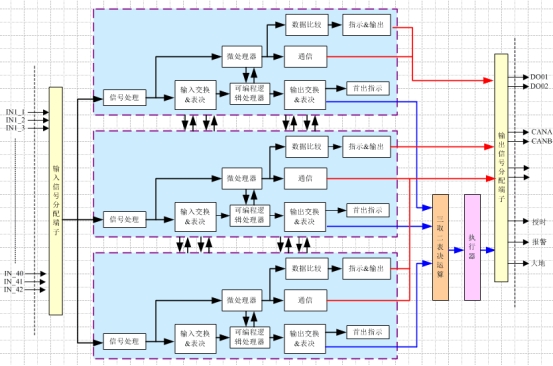
(8) Three redundant structure
Can work independently without configuration, can communicate directly with the outside world through Modbus
(9) Flexible combination
The high-reliability ETS system is part of DCS and can be seamlessly connected to DCS. Any point inside can be used as SOE and historical curves. The points inside can be monitored in real time in DCS, which can be used to make historical trends and facilitate search.
The ETS system combination is very flexible and can be combined into different logical functions according to actual needs, which can adapt to the security protection needs of various systems.

Figure 3.13.2-3 High-reliability ETS three redundant working principle diagram